Manual
Please read also the article text “Calibration Manual” on this website, it contains further information! (the pdf file “Calibration Manual” on that page can be read later…).
Following parts are needed: see section “Parts that are needed for the PCB” here.
The Pcb can be ordered here.
All components except the two 2×10 female pin connector are soldered to the top side of the PCB.
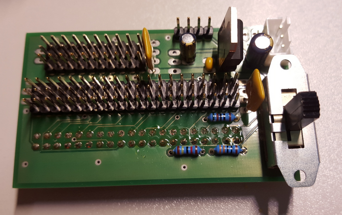
Front look of the final PCB:
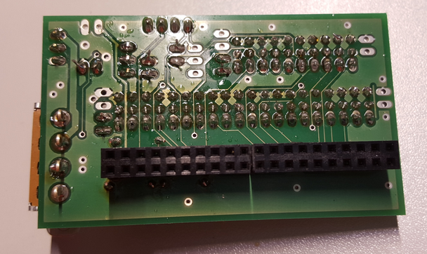
Back look of the final PCB:
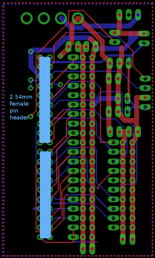
Solder the components as seen in the pictures and in the image below. Be sure to use the right side and the right holes for the pin headers (as sometimes one hole is free besides the pin headers, it is easy to get the wrong holes…)
PCB front with small components:
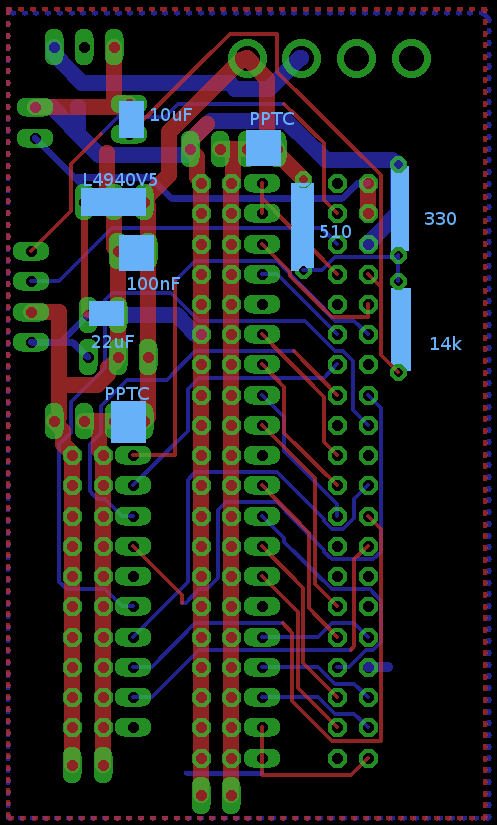
Make sure you solder the L4940V5 in the correct direction, see first picture on this page (metal to the left). The + (longer pin) of the 10uF and 22uF has to be at the correct side, see picture below.
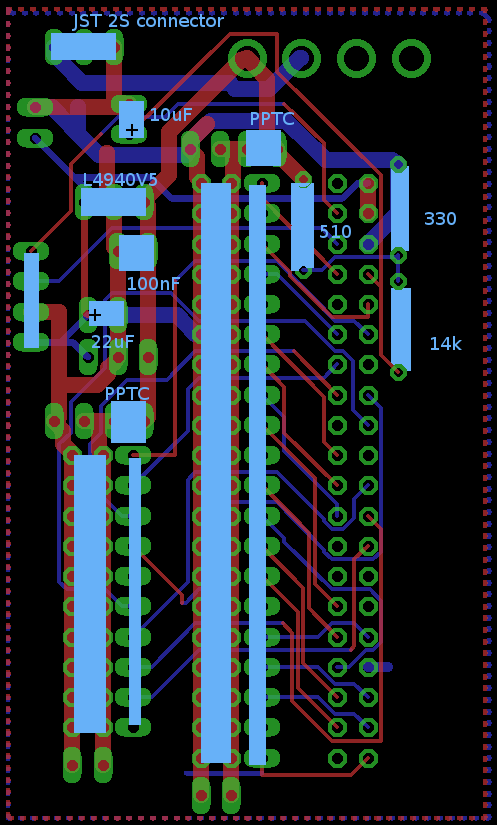
PCB front with pin headers and JST connector added. Note: The 4 pin interface on the left side that is not labeled is used to connect the acceleration board. On the 4 big holes on the top you can connect a on/off switch. If you don’t have one, you can just connect the 2 left holes with some solder:
PCB Back side:
Hallo Johannes
Was war die Idee mit dem zweiten (vorgesehenen) Spannungsregler im Schema und auf dem PCB?
Herzliche Grüsse
Matthias
Hallo Matthias,
die Idee war eine zu hohe Leistung im Spannungsregler zu vermeiden. Ist aber eigentlich nicht nötig, einer kommt gut alleine zurecht. 2 müsste man eigentlich auch etwas anders verschalten, dann verliert man aber wieder Spannung.
Viele Grüße!
Johannes
Hallo Johannes
Sehe ich das richtig dass der Spannungsteiler auf der Platine dazu da ist, die Batteriepsannung zu monitoren, dass möglichst keine Tiefentladung stadtfindet?
Die geteilte Batterispannung wird über ein RC-Glied auf GPIO14 (pin#8) gelegt und vom supply_voltage.py (ros node “supply_voltage”) gemessen.
Herzliche Grüsse
Matthias
Hallo Matthias,
ja genau dazu ist er gedacht, zusammen mit dem von dir erwähnten Programm, gutes backwards engineering ;-)!
In der node muss man glaub 1-2 Konstanten richtig einstellen, und dann nochmal dafür sorgen, dass er zum Beispiel etwas spricht wie “Batterie leer”. Muß man nur auf dem entsprechenden Topic für Sprachausgabe eine Nachricht veröffentlichen. Müßtest du nochmal genauer in die Node schauen…
Viele Grüße!
Johannes