Please download the calibration manual here and additionally take the instruktions below into account:
Please connect the servos to the PCB as follows:
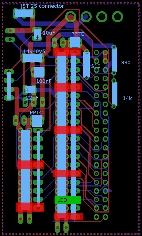
- Do not use the red marked areas. These are left free and not connected to the Raspberry Pi in oder to allow enough space for all connectors to fit on the board (5 connectors in a row would not fit!)
- Connect the LED for the mouth to the indicated place.
- To create the connection of the LED to the PCB Board: Use one of the servo extension cables and cut the side that is not plugged into the PCB. Solder the LED with shorter side to the black (minus) cable, solder the LED with longer side (plus) to the signal cable (usually yellow or wihte). As the LED will blink 15 times per second and therefore has a short on time, it will not break even if for a short time the voltage of 3.3V is bigger then specified for the LED.
- Connect the left side of the robot servos (5x leg + 3x arm) all to the left connector port and the right side all to the right connector port. This ensures that each of the sites has its own PPTC for shutting down the current in case of high load to the Servos.
- In case your PPTC is triggered too often, you can replace it with a bigger one or just short it. However the risk is that your servos break in case you do not realize that too much current is drawn and the servos get hot, which can happen quite often, especially if the weight of the robot is on one leg only during programming.
- It is recommended to connect all servos to the PCB once before the calibration according aboves manual is startet. Connect your Raspberry with the Wifi (see manual above) and connect the PC SW to the robot. then klick on “move & all servos on”. All servos should be set to a position by this. If a servo is not moving, try another connector for that servo and maybe check the soldering connections on the PCB. You can also check if all servos move by moving the sliders in the PC SW around.
Hallo Johannes
Einige Fragen zum PDF Calibration:
Die Fotos des Servo-Boards zeigen eine (vermutlich) frühe Version Deines Boards. Da gab es noch keinen Spannungsregeler oder sonstige Bauteile. Folglich sieht man auch keine Stromversorgung..
Gehe ich richtig in der Annahme, dass Du dazumals die Servos via Raspberry versorgt hast, dies aber nun nicht mehr möglich ist? D.h. für die Kalibrierung muss zwingend entweder die Batterie oder ein Netzteil an das Board angeschlossen werden. (und entweder Schalter anlöten oder Kontakte Kurzschliessen).
Wäre es nicht sinnvoll vor dem ersten Anschliessen einer Batterie ans Board, dieses auszutesten? D.h. ich würde vorschlagen ein Netzteil anschliessen und langsam die Spannung hochdrehen. Dabei den Stromkonsum beobachten. Steigt er schnell an, ist was faul. Sonst hoch bis 6.3 V. Dann sollte die 5V Spannung gemessen werden, die den Raspberry speisen wird. Erst wenn das erfolgreich war, würde ich das Board montieren und in Betrieb nehmen.
Im PFD unter ‘D Connect your mobile phone’ schreibst Du, dass man mit einem browser auf Port 8000 verbinden kann. Gehe ich richtig in der Annahme, dass das im PI3 Image (noch) nicht funktioniert? Welcher Service steckt dahinter? Ich kann das leider nicht auf einem Pi2 Image nachsehen, weil dieses wie schon geschrieben, nicht bootet;-)
Danke und Gruss
Matthias
Hallo Matthias,
ja, das war eine frühere Version. Per Raspberry kann man die Servos leider nicht versorgen, da reicht der Strom bei weitem nicht aus. Ich habe die Stromversorgung per Servokabel angeschlossen.
Ja, für die Kalibrierung muss das Netzteil oder die Batterie angeschlossen werden.
Ja, mit der Inbetriebnahme vorsichtig zu sein ist besser. Vor allem dürfen keine Kurzschlüsse vom + der Spannungsversorgung zu den Signalleitungen auf dem PCB sein. Sonst geht der Raspberry schnell kaputt.
Ja, die HTTP Verbindung funktioniert beim Pi3 Image wahrscheinlich noch nicht. Dahinter steckt eine modifizierte Version des Mjpg-Streamers.
Ich muss mir das Pi3 Image nochmal anschauen, sobald ich dazu komme…
Viele Grüße!
Johannes
Hallo Johannes
Ich habe Probleme mit dem PI3 Image. Ich kann von der LiveCode SW aus verbinden und def ‘Alle Servos On and Move’ Befehl absetzen. Ich sehe auch auf dem PI3 im entsprechenden ros log, dass die einzelnen Befehle zum Ansteuern der einzelnen Servos ankommen, aber nichts bewegt sich. Ich habe es mit zwei verschiedenen Servos an verschiedenen Pin Positionen versucht, ohne Erfolg. Die Versorgungsspannung ist vorhanden. Hast Du eine Ahnung woran das liegen könnte? Sonst muss ich selber weiter debuggen..
Ich würde segr gerne die Funktionalität mit dem PI2 Image vergleichen. Aber wie gesagt bootet dieses nicht. Icvh konnte es heute auf einem anderen Linux System mounten und die Filesysteme scheinen soweit in Ordnung zu sein. Ebenfalls konnte ich mich so etwas im Code umschauen und habe gesehen, dass der HTTP Server mittels eines PHP Scripts implementiert ist, welcher auf Port 80 hört. Der mjpg-streamer hört auf Port 8000 und ist nur für Video da, richtig?
Wenn ich ein lauffähiges PI2 Image hätte, könnte ich die fehlende Funktionaliät im PI3 Image selber implementieren resp. portieren. Wenn Du also mal ein paar Minuten investieren könntest, wäre das super:-)
Vielen Dank für Deine Unterstützung und herzliche Grüsse
Matthias
Hallo Matthias,
schliß mal noch ein paar mehr Servos an und klick auf “Calibrate Robot” und “Allocate Joint No”. Dann geht er nacheinander alle Servos durch und bewegt sie ein paar Grad. Die Nummer des Servos, das sich bewegt, musst du dann eingeben. Wenn sich keins bewegt “99” eingeben. Klappt das? Die “zero_point_correction” im Ordner “/home/ubuntu/catkin_ws/src/gero_move/data” wird dabei neu geschrieben. Dort steht die Zuordnung der Nummern in der PC-SW zu dem Servo. Versorgt sind die Servos? Kannst du prüfen, ob an den Signalpinnen ein PWM Signal anliegt? Wenn du die Node mit “rosrun gero_move servo_driver” startest, steht dort irgendwo eine Fehlermeldung?
Ich bin gerad zu Hause, hatte vorher keinen Zugriff auf den Roboter. Schau mir das Pi2 image nochmal an.
Gestartet wird der mjpg streamer von dieser Datei “/home/ubuntu/catkin_ws/src/gero_control/scripts/streaming.sh” dort steht aber noch der Pfad vom Pi2 image. Änder mal in der Datei path=”/home/pi/ros/src/gero_control/mjpg-streamer/mjpg-streamer/” in path=”/home/ubuntu/catkin_ws/src/gero_control/mjpg-streamer/mjpg-streamer/”, könnte schon sein dass die Bildübertragung dann klappt.
Viele Grüße!
Johannes
Hallo Johannes
Vielen Dank schon mals. Komme leider erst in einer Woche dazu weitere Tests zu machen..
Gebe dann Feedback:-)
Herzliche Grüsse
Matthias
Hallo Matthias,
so, ich hab gerade nochmal ein neues Image von der Pi2 SD Karte erstellt und auf eine andere übertragen, das funktioniert. Hochladen muss ich das Image noch, das wird ein paar Tage dauern.
Die Ansteuerung für die Servos ist von hier “https://github.com/richardghirst/PiBits/tree/master/ServoBlaster” evtl. muss auch neu erstellt werden: im Verzeichnis “/home/ubuntu/catkin_ws/src/gero_move/user works Pi2” “make servod” eingeben. Dann mit “sudo ./servod” starten. Wenn das ohne Fehlermeldung läuft, die Datei “servod” ein Verzeichnis nach oben kopieren und nochmal probieren.
Viele Grüße!
Johannes